
Abstract
Knowledge of DC circuit analysis (Chaps. 2, 3, and 4)
Access this chapter
Tax calculation will be finalised at checkout
Purchases are for personal use only
Author information
Authors and Affiliations
Appendices
Summary
Term | Meaning/Figure | |
|---|---|---|
Steady-state AC voltage (steady-state alternating current) | \( \upsilon (t)={V}_m\cos \left(\omega \kern0.1em t+\varphi \right) \) \( {V}_m>0 \) is the voltage amplitude [V] \( \omega =2\pi \kern0.1em f>0 \) is the angular frequency [rad/s] \( f>0 \) is the frequency [Hz] \( T=1/f>0 \) is the period [s] \( -\pi \le \varphi \le \pi \) is the phase [rad] or [deg] |
|
Leading/lagging |
| |
Euler’s identity | \( {e}^{j\alpha}=\cos \alpha +j\sin \alpha \), \( {e}^{j\pi /2}=j \), \( {e}^{- j\pi /2}=-j \) | |
Time-domain signal υ(t) versus its phasor V; phasor diagram |
| |
Complex phasors and impedances \( {\displaystyle \begin{array}{c}{\mathbf{Z}}_R=R\\ {}{\mathbf{Z}}_C=\frac{1}{j\omega C}\\ {}{\mathbf{Z}}_L= j\omega L\end{array}} \) |
| |
Meaning of complex impedance |
| |
Solution for an AC circuit |
| |
Proof of the conversion from time domain to frequency domain | \( -{\upsilon}_S(t)+{\upsilon}_R(t)+{\upsilon}_C(t)=0\Rightarrow \) \( -\operatorname{Re}\left({\mathbf{V}}_S{e}^{j\omega \kern0.1em t}\right)+\operatorname{Re}\left({\mathbf{V}}_R{e}^{j\omega \kern0.1em t}\right)+\operatorname{Re}\left({\mathbf{V}}_C{e}^{j\omega \kern0.1em t}\right)=0\Rightarrow \) \( \operatorname{Re}\left(-{\mathbf{V}}_S{e}^{j\omega \kern0.1em t}+{\mathbf{V}}_R{e}^{j\omega \kern0.1em t}+{\mathbf{V}}_C{e}^{j\omega \kern0.1em t}\right)=0\Rightarrow \) \( -{\mathbf{V}}_S{e}^{j\omega \kern0.1em t}+{\mathbf{V}}_R{e}^{j\omega \kern0.1em t}+{\mathbf{V}}_C{e}^{j\omega \kern0.1em t}=0\Rightarrow \) \( -{\mathbf{V}}_S+{\mathbf{V}}_R+{\mathbf{V}}_C=0 \) | |
Analytical solution method (calculator) |
| |
Numerical solution method (MATLAB) |
| |
Source transformation; Thévenin and Norton equivalent circuits |
\( {\mathbf{Z}}_T={\mathbf{Z}}_N,{\mathbf{V}}_T={\mathbf{Z}}_T{\mathbf{I}}_N,{\mathbf{I}}_N=\frac{{\mathbf{V}}_T}{{\mathbf{Z}}_T} \) | |


Problems
2.1 8.1 Harmonic Voltage and Current: Phasor
8.1.1 Harmonic Voltages and Currents
8.1.2 Phase: Leading and Lagging
Problem 8.1
-
A.
Write a general expression for the AC harmonic voltage signal (steady-state AC voltage) using the cosine function.
-
B.
Identify amplitude, angular frequency, and phase.
-
C.
Write relations between the angular frequency, frequency, and the period.
Problem 8.2
-
A.
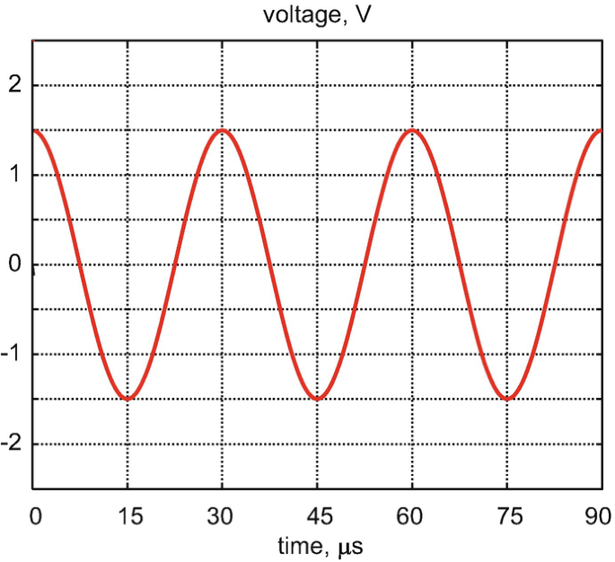
Determine frequency in Hz, angular frequency in rad/s, and amplitude of the harmonic voltage signal shown in the figure below (show units for every quantity).
-
B.
Write the AC voltage in the form of a cosine function with the corresponding amplitude, frequency, and phase.

Problem 8.3
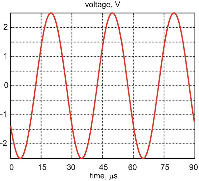
Repeat problem 8.2 for the voltage signal shown in the figure below.

Problem 8.4
Repeat problem 8.2 for a harmonic voltage signal with a DC offset shown in the figure below.

Problem 8.5
-
A.
Determine frequency in Hz, angular frequency in rad/s, amplitude, and phase (versus the base cos ω t signal) of the harmonic voltage shown in the figure below (show units for every quantity).
-
B.
Write the AC voltage in the form of a cosine function with the corresponding amplitude, frequency, and phase.

Problem 8.6
Repeat problem 8.5 for the voltage signal shown in the figure below.

Problem 8.7
Repeat problem 8.5 for the voltage signal shown in the figure below.

Problem 8.8
Repeat problem 8.5 for the voltage signal shown in the figure below.

Problem 8.9
An AC voltage in a circuit is given by \( \upsilon (t)=10\cos \left(2\pi 50t\right)\kern0.5em \left[\mathrm{V}\right] \). Using software of your choice, plot the voltage to scale over the time interval of two periods, i.e., \( 0\le t\le 2T \). Label the axes.
Problem 8.10
An AC voltage in a circuit is given by the voltage expression \( \upsilon (t)=10\cos \left(1000t-\pi /3\right)\kern0.5em \left[\mathrm{V}\right] \). Using software of your choice, plot the voltage to scale over the time interval of four periods, i.e., \( 0\le t\le 4T \). Label the axes.
Problem 8.11
The reference voltage is shown by a solid curve in the figure; the AC voltage under study is shown by a dashed curve. Determine if the AC voltage under study leads or lags the reference voltage, and, if so, by how many degrees.

Problem 8.12
Repeat problem 8.11 for the voltage signal shown in the figure below.

Problem 8.13
Repeat problem 8.11 for the voltage signal shown in the figure below.

Problem 8.14
Determine the frequency in Hz, period in s, amplitude in V, and phase in degrees (versus the base cosine signal) of the voltage signal in the form \( \upsilon (t)=15\sin \left(100\;t+{45}^{{}^{\circ}}\right)\kern0.5em \left[\mathrm{V}\right] \). Hint: Convert the signal to the base cosine form first.
Problem 8.15
Determine the frequency in Hz, period in s, amplitude in V, and phase in radians (versus the base cosine signal) of the voltage signal in the form \( \upsilon (t)=15\sin \left(1000\;t-{35}^{{}^{\circ}}\right)\kern0.5em \left[\mathrm{V}\right] \). Hint: Convert the signal to the base cosine form first.
Problem 8.16
Determine the frequency in Hz, period in s, amplitude in V, peak-to-peak value in V, and phase in radians (versus the base cosine signal) of the voltage signal in the form \( \upsilon (t)=5\sin \left(100\;t+{225}^{{}^{\circ}}\right)\kern0.5em \left[\mathrm{V}\right] \). Hint: Convert the signal to the base cosine form first.
Problem 8.17
The AC voltage is given by a combination of two sinusoids:
-
A.
\( \upsilon (t)=1\kern-0.1em \sin \kern-0.1em \left(\omega \kern0.1em t+\pi /2\right)-2\kern-0.1em \sin \kern-0.1em \left(\omega \kern0.1em t-\pi /2\right) \)
-
B.
\( \upsilon (t)=1\sin \kern-0.1em \left(\omega \kern-0.1em t+\pi /2\right)-2\sin \left(\omega \kern-0.1em t-\pi /3\right) \)
Convert this voltage to the basic cosine form \( \upsilon (t)={V}_{\mathrm{m}}\cos \left(\omega \kern0.1em t+\varphi \right) \) and determine the amplitude and the phase (versus the base cosine signal).
Hint: Trigonometric identities may be found in the summary to this chapter.
8.1.4 Definition of a Phasor
8.1.5 From Real Signals to Phasors
8.1.6 From Phasors to Real Signals
Problem 8.18
Determine the phasors for the real-valued AC voltages and currents. Show units. Express all phase angles in radians.
Problem 8.19
Determine the phasors for the real-valued AC voltages and currents. Use the shorthand notation ∠ for the complex exponent. Show units. Express all phase angles in degrees.
Problem 8.20
The phasors of the AC voltage and current are given by
The AC source has the angular frequency ω. Restore the corresponding real-valued voltages and currents. Show units; express all phase angles in radians.
Problem 8.21
The phasors of the AC voltage and current are given by
The AC source has the angular frequency ω. Restore the corresponding real-valued voltages and currents as functions of time. Show units. Express all phase angles in radians.
Problem 8.22
The phasors of the AC voltage and current are given by
The AC source has the angular frequency ω. Restore the corresponding real-valued voltages and currents. Show units; express all phase angles in degrees.
8.1.7 Polar and Rectangular Forms: Phasor Magnitude
8.1.8 Operations with Phasors and Phasor Diagram
Problem 8.23
A complex number V is given by \( \mathbf{V}=4+j\;2 \).
-
A.
Convert it into polar form; express the phase angle in degrees.
-
B.
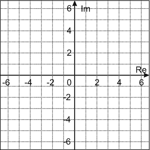
Plot the number on the phasor diagram.
-
C.
If this number is a phasor of a voltage signal with the units of volts, what is the voltage signal in time domain? Assume the angular frequency ω.

Problem 8.24
Repeat problem 8.23 for \( \mathbf{V}=4\exp \left(- j\pi /6\right) \), but convert this number to the rectangular form.
Problem 8.25
Repeat problem 8.23 for \( \mathbf{V}=25/\left(3+j4\right) \).
Problem 8.26
Phasors of three AC voltage signals are shown in Fig. 8.8. Every division in the figure corresponds to 1 V. The AC source has the angular frequency ω. Restore the corresponding real-valued voltages in time domain. Show units. Express all phase angles in radians.
Problem 8.27
The phasors of the AC voltage and current are given in the rectangular form:
The AC source has the angular frequency ω. Restore the corresponding real-valued voltages and currents. Show units, express all phase angles in radians.
Problem 8.28*
Solve the previous problem using MATLAB. Present the corresponding MATLAB script.
Problem 8.29
The phasors of the AC voltage and current are given in the rectangular form:
The AC source has the angular frequency ω. Restore the corresponding real-valued voltages and currents. Show units; express all phase angles in radians.
Problem 8.30
Solve the previous problem using MATLAB. Present the corresponding MATLAB script.
Problem 8.31
Two phasor voltages are shown in the phasor diagram. The AC source has the angular frequency ω. Restore the corresponding real-valued voltages. Show units. Express all phase angles in radians.

Problem 8.32
Phasors of two AC current signals are shown in the following figure. The AC source has the angular frequency ω. A sum of two current signals is desired. Restore the real-valued current corresponding to the sum of three signals in time domain. Express the phase angle in degrees.

Problem 8.33
Phasors of three AC voltage signals are shown in Fig. 8.8. Every division in the figure corresponds to 1 V. The AC source has the angular frequency ω. A sum of three voltage signals is desired. Restore the real-valued voltage corresponding to the sum of three signals in time domain. Express the phase angle in degrees.
Problem 8.34
Solve the previous problem using MATLAB. Present the corresponding MATLAB script.
Problem 8.35
Voltages of two series elements, shown in the figure below,

are given by
-
A.
Draw the phasor diagram and show phasors V1, V2 to scale as two vectors in the complex plane.
-
B.
Show the sum \( \mathbf{V}={\mathbf{V}}_1+{\mathbf{V}}_2 \) as a vector in the complex plane.
-
A.
Find voltage υ(t) between terminals a and b using the phasor method. Express the phase angle in degrees.
-
C.
Does voltage υ1(t) lag or lead voltage υ2(t)?
Problem 8.36
Repeat the previous problem for:
Problem 8.37
Electric currents through two parallel circuit elements are shown in the following figure:

The current expressions are given by
-
A.
Draw the phasor diagram and show phasors I1, I2 to scale as two vectors in the complex plane.
-
B.
Show the difference \( \mathbf{I}={\mathbf{I}}_1-{\mathbf{I}}_2 \) as a vector in the complex plane.
-
C.
Find the net current i(t) of the parallel combination using the phasor method. Express the phase angle in degrees.
-
D.
Does the net current i(t) lag or lead current i1(t)?
2.2 8.2 Impedance
8.2.1 The Concept of Impedance
8.2.2 Physical Meaning of the Impedance
Problem 8.38
Prove that the impedance of the inductor, \( {\mathbf{Z}}_{\mathrm{L}}= j\omega \kern0.1em L \), has units of ohms.
Hint: The imaginary unit j is dimensionless. However, in the context of phasors, it may be assigned the units of rad−1.
Problem 8.39
Prove that the impedance of the capacitor, \( {\mathbf{Z}}_{\mathrm{C}}=\frac{1}{j\omega C} \) has units of ohms.
Hint: The imaginary unit j is dimensionless. However, in the context of phasors, it may be assigned the units of rad−1.
Problem 8.40
An ECE student discovers a “new” dynamic passive circuit element N (in addition to the inductor and the capacitor) that is described by the voltage-to-current relation \( {\upsilon}_N=N\frac{d^2{i}_N}{d{t}^2} \) where N is a positive constant:
-
A.
Obtain the impedance for this circuit element.
-
B.
Do you think such a circuit element may exist? Why or why not? Hint: The real part of the impedance is the element resistance. If the resistance is negative, the element delivers power instead of absorbing it.
Problem 8.41
Another ECE student discovers a “truly new” dynamic passive circuit element N (in addition to the inductor and the capacitor) that is described by the voltage-to-current relation \( {\upsilon}_N=N\frac{d^3{i}_N}{d{t}^3} \) where N is a constant:
-
A.
Obtain the impedance for this circuit element.
-
B.
Do you think such a circuit element may exist? Why or why not? Hint: The real part of the impedance is the element resistance. If the resistance is negative, the element delivers power instead of absorbing it.
Problem 8.42
For three AC circuits shown in the following figure, find the impedance of the resistor, inductor, and capacitor (when present). Show units. Express the result in rectangular form. Also express the result in polar form using the shorthand notation \( \angle \). Determine the magnitude of the impedance. Does the strength of the power supply have an effect on the obtained impedance values?

Problem 8.43
Repeat problem 8.42 if the AC voltage power supply in every figure is replaced by an alternating current power supply with the same frequency and amplitude of 0.5 A.
Problem 8.44
Voltages (dashed curves) and the corresponding currents (solid curves) for three unknown circuit elements are shown in the figure below.

Determine:
-
A.
The type of the element (resistor, capacitor, or inductor)
-
B.
The value of the corresponding resistance, inductance, or capacitance
Note that the angular frequency is different in every case.
Problem 8.45
Voltages (dashed curves) and currents (solid curves) for three unknown circuit elements are shown in the figure below.

Determine:
-
A.
The type of the element (resistor, capacitor, or inductor)
-
B.
The value of the corresponding resistance, inductance, or capacitance
Problem 8.46
Phasor voltages and currents for three unknown circuit elements are shown in the figure below. Determine the type of the element (R, L, or C) and the value of R, L, or C.

Problem 8.47
Phasor voltages and phasor currents for three unknown circuit elements are shown in the figure below. Determine the type of the element (R, L, or C) and the value of R, L, or C when appropriate.

Problem 8.48*
The following MATLAB script plots the real-valued signals in time domain corresponding to the phasor voltage \( \mathbf{V}=5\angle {30}^{{}^{\circ}}\kern0.5em \left[\mathrm{V}\right] \) and to the phasor current \( \mathbf{I}=2\angle -{60}^{{}^{\circ}}\kern0.5em \left[\mathrm{A}\right] \) for an inductor.
clear all
f = 2e6; % frequency, Hz
T = 1/f; % period, sec
dt = T/100; % sampling int.
t = [0:dt:2.5*T]; % time vector
vL = 5*cos(2*pi*f*t+pi/6); % voltage
iL = 2*cos(2*pi*f*t-pi/3); % current
t = t/T; % time in periods
plot(t, vL, 'b');
grid on; hold on;
plot(t, iL, 'r');
xlabel('t/T');
ylabel('voltage/current')
Modify the script and plot the real- valued voltages and currents corresponding to the phasors shown in the phasor diagrams for Problem 8.46.
Problem 8.49
Repeat the previous problem for the phasors shown in the phasor diagrams for Problem 8.47.
2.3 8.3 Principles of AC Circuit Analysis
8.3.1 AC Circuit Analysis: KVL, KCL, and Equivalent Impedances
8.3.2 Complete Solution for an AC Circuit: KVL and KCL on Phasor Diagram
Problem 8.50
For the AC circuit element combinations shown in the figure that follows,

-
A.
Find the equivalent impedance Zeq in polar form given that \( \omega =10000\kern0.5em \mathrm{rad}/\mathrm{s} \), \( C=0.1\kern0.5em \upmu \mathrm{F} \), \( L=100\kern0.5em \mathrm{mH} \), \( R=1\kern0.5em \mathrm{k}\Omega \).
-
B.
Plot the result for the partial impedances and for Zeq on the corresponding phasor diagram.
Problem 8.51
Find Zeq in the polar form for the circuit element combination shown in the figure below when \( \omega =100,000\kern0.5em \mathrm{rad}/\mathrm{s} \), \( C=100\kern0.5em \mathrm{nF} \), \( L=1\kern0.5em \mathrm{mH} \), \( R=100\kern0.5em \Omega \).

Problem 8.52
For three circuit element combinations shown in the figure below,
find Zeq given that \( \omega =2000\kern0.5em \mathrm{rad}/\mathrm{s} \), \( C=5\kern0.5em \upmu \mathrm{F} \), \( L=50\kern0.5em \mathrm{mH} \), \( R=1\kern0.5em \mathrm{k}\Omega \).

Problem 8.53
A complex impedance of any circuit may be written in the form \( \mathbf{Z}=R+ jX \) where R is called the resistance and X is called the electrical reactance or simply the reactance. An engineer measures a reactance of 2 Ω over an inductor at 60 Hz. What is the inductance?
Problem 8.54
The same engineer measures a reactance of −1 kΩ over a capacitor at 60 Hz. What is the capacitance?
Problem 8.55
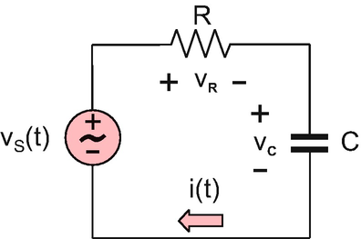
For the circuit shown in the figure below, \( {\upsilon}_{\mathrm{S}}(t)=10\cos \omega t\kern0.5em \left[\mathrm{V}\right],\omega =10,000\kern0.5em \mathrm{rad}/\mathrm{s},\kern0.5em C=1\kern0.5em \upmu \mathrm{F},\kern0.5em R=100\kern0.5em \Omega \):
-
A.
Find phasor current I and phasor voltages, VR, VC, and construct the voltage phasor diagram for phasors VR, VC, VS.
-
B.
Find voltages across the resistor and capacitor, υR(t) and υC(t), as functions of time.

Problem 8.56
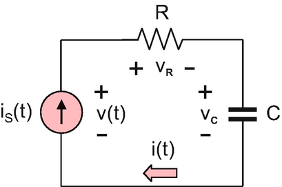
For the circuit shown in the figure below, \( {i}_{\mathrm{S}}(t)=1\cos \omega t\kern0.5em \left[\mathrm{A}\right] \) and \( \omega =10,000\kern0.5em \mathrm{rad}/\mathrm{s},C=1\kern0.5em \upmu \mathrm{F},R=100\Omega \).
-
A.
Find phasor voltages VR, VC, V and construct the voltage phasor diagram for phasors V, VR, VC.
-
B.
Find voltages across the resistor and capacitor, υR(t) and υC(t), as functions of time.

Problem 8.57
Repeat problem 8.55 when \( C=2.2\kern0.5em \upmu \mathrm{F} \). The rest of the parameters are the same.
Problem 8.58
Repeat problem 8.55 when \( C=2.2\kern0.5em \upmu \mathrm{F} \) and \( f=500\kern0.5em \mathrm{Hz} \). The rest of the parameters are the same.
Problem 8.59
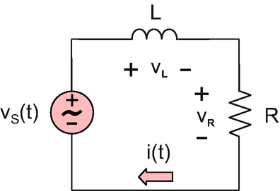
In the circuit shown in the figure below, \( {\upsilon}_{\mathrm{S}}(t)=12\cos \omega t\ \left[\mathrm{V}\right],\omega =10,000\ \mathrm{rad}/\mathrm{s},L=1\kern0.5em \mathrm{mH},\kern0.5em R=10\kern0.5em \Omega \):
-
A.
Find phasor current I and phasor voltages, VR, VL, and construct the voltage phasor diagram for phasors VR, VC, VS.
-
B.
Find voltages across the resistor and inductor, υR(t) and υL(t), as functions of time.

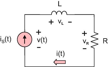
Problem 8.60
For the circuit shown in the figure, \( {i}_{\mathrm{S}}(t)=1\cos \omega t\ \left[\mathrm{A}\right] \) and \( \omega =10,000\ \mathrm{rad}/\mathrm{s},L=10\kern0.5em \mathrm{mH},\kern0.5em R=100\kern0.5em \Omega \):
-
A.
Find phasor voltages, VR, VL, V and construct the voltage phasor diagram for phasors V, VR, VC.
-
B.
Find voltages across the resistor and inductor, υR(t) and υL(t), as functions of time.

Problem 8.61
Repeat Problem 8.59 when \( L=1.9\kern0.5em \mathrm{mH} \). Assume the other parameters to be the same.
Problem 8.62
Repeat Problem 8.59 when \( L=6.8\kern0.5em \mathrm{mH} \) and \( f=1000\kern0.5em \mathrm{Hz} \). The rest of the parameters are the same.
8.3.3 Source Transformation
8.3.4 Thévenin and Norton Equivalent Circuits
8.3.5 Summary of AC Circuit Analysis at a Single Frequency
8.3.6 Multi-frequency AC Circuit Analysis: Superposition Principle
Problem 8.64
A current source with the phasor current IN and in parallel with the impedance ZN shown in the following figure is equivalent to a voltage source with the phasor voltage VT and in series with the impedance ZT. Determine VT and ZT given that \( {\mathbf{I}}_N=2+j3\kern0.5em \mathrm{A} \), \( {\mathbf{Z}}_N=2-j3\kern0.5em \Omega \). Express your result in the polar form.

Problem 8.65
Determine phasor voltage V1 in the AC circuit shown in the following figure using the method of source transformation. The impedance values are given at the frequency of interest.

Problem 8.66
Find the Thévenin equivalent circuit, i.e., VT and ZT, for the circuit shown in the figure below when \( \omega =377\ \mathrm{rad}/\mathrm{s},L=26.5\ \mathrm{mH},R=10\ \Omega, C=220\ \upmu \mathrm{F},{\upsilon}_{\mathrm{S}}(t)=10\cos \omega t\kern0.5em \left[\mathrm{V}\right]. \)

Problem 8.67
Find the Thévenin equivalent circuit, i.e., VT and ZT, for the circuit shown in the figure below when \( \omega =377\kern0.5em \mathrm{rad}/\mathrm{s},L=26.5\ \mathrm{mH},R=10\ \Omega, C=500\ \upmu \mathrm{F},\mathrm{and}\ {V}_{\mathrm{S}}(t)=10\cos \omega \kern0.1em t\kern0.5em \left[\mathrm{V}\right]. \)

Problem 8.68
Describe the meaning of the superposition principle for multifrequency AC circuits in your own words.
Problem 8.69
Find real-valued voltage υR(t) across the resistor for the circuit in the following figure using the superposition principle. You are given \( {V}_1=10\kern0.5em \mathrm{V},\kern0.5em {V}_2=1\kern0.5em \mathrm{V} \). The AC frequencies are \( {\omega}_1=377\kern0.5em \mathrm{rad}/\mathrm{s} \) and \( {\omega}_2=3{\omega}_1 \), respectively.

Rights and permissions
Copyright information
© 2019 Springer Nature Switzerland AG
About this chapter

Cite this chapter
Makarov, S.N., Ludwig, R., Bitar, S.J. (2019). Steady-State AC Circuit Fundamentals. In: Practical Electrical Engineering. Springer, Cham. https://doi.org/10.1007/978-3-319-96692-2_8
Download citation
DOI: https://doi.org/10.1007/978-3-319-96692-2_8
Published:
Publisher Name: Springer, Cham
Print ISBN: 978-3-319-96691-5
Online ISBN: 978-3-319-96692-2
eBook Packages: EngineeringEngineering (R0)